The hydraulic system is the power source of a hydraulic injection molding machine. An electric motor drives a pump, the pump sends oil under pressure to a block of valves, and the valves direct it to the cylinders and the hydraulic motor that move the mold, the injection unit, the screw and the ejector. The numbered drawing above shows the main parts, from the oil tank to a cylinder; this guide explains what each one does, the faults that show up most often, and what to send when you need a replacement.
How the hydraulic system works
The oil travels in a loop. The pump draws it from the tank through a suction filter and delivers it to the valve manifold. The valves open a path to one actuator at a time (sometimes two), and the oil pushed out of the other side of the actuator returns through the oil cooler to the tank.
During a cycle, the valves switch the oil in roughly this order:
- Mold close and clamp. The clamp cylinder closes the mold quickly, slows down for mold protection, then builds the clamping force, directly or through the toggle.
- Carriage forward. The carriage cylinders push the injection unit forward until the nozzle touches the mold.
- Injection and hold. The injection cylinder drives the screw forward at the set speed, then holds pressure while the part cools.
- Screw recovery. While the part cools, the plasticizing motor turns the screw to melt the next shot, against the set back pressure.
- Mold open and ejection. The clamp opens and the ejector cylinder pushes the part out.
Each step needs its own pressure and flow. On a machine with a constant-speed motor and a fixed pump, a proportional valve sets them and the surplus oil returns to the tank. With a variable piston pump, the pump control reduces the pump's displacement instead. On a servo pump machine, the servo motor changes the pump speed. The hydraulic circuit page shows how these circuits are drawn and how to read the diagram in your machine manual.
The parts of the hydraulic system
Oil tank
The tank, usually built into the machine base, holds the oil. Returning oil settles there and sheds heat and air before the pump draws it again. A sight glass shows the level, and a breather lets air in and out as the level changes. See the oil tank page.
Suction filter
A strainer on the pump's suction line inside the tank keeps dirt and metal particles out of the pump; many also carry a magnet for iron particles. A blocked suction filter starves the pump and makes it noisy. Return-line filters, where fitted, clean the oil coming back. See the oil filter page.
Electric motor or servo motor
On conventional machines a three-phase induction motor drives the pump at constant speed. Energy-saving machines use a servo motor and drive that turn the pump only as fast as each step of the cycle needs. See servo pump systems.
Coupling and bell housing
The bell housing bolts the pump to the motor flange and keeps the two shafts in line; a flexible jaw coupling inside carries the torque and absorbs vibration. A worn coupling insert often shows up as a knock at start-up. See the pump coupling page.
Hydraulic pump
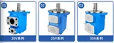
The pump turns the motor's rotation into oil flow. Injection molding machines use vane pumps, axial piston pumps and gear pumps. Constant-speed machines mostly use vane or piston pumps, and servo-hydraulic machines often use internal gear pumps. The hydraulic pump types page compares them and explains how to identify yours. With the motor, coupling and tank, the pump forms the hydraulic power unit.
Pressure gauge and pressure transducer
A pressure gauge shows the system pressure at a glance, so the operator can check the settings and notice a pressure loss early. A pressure transducer measures pressure electrically and sends the signal to the controller or the servo drive for display, alarms and pressure control.
Valve manifold
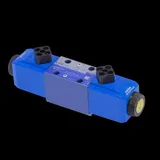
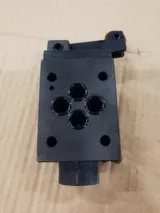
The valve manifold is a steel block drilled with oil passages, with the valves bolted onto it or screwed into it. Solenoid directional valves start, stop and reverse each movement, proportional valves set its pressure and speed, cartridge valves switch the large flows of the clamp and injection circuits, and check valves let oil flow one way only.
Relief valve
The relief valve limits the highest pressure in the system. When the pressure goes above its setting, it opens and sends oil to the tank, protecting the pump, hoses and cylinders.
Hydraulic cylinders and motor
Cylinders turn oil pressure into straight-line force for clamping, injecting, ejecting and moving the injection unit: see the clamp cylinder guide and the injection cylinder. The screw is turned by a low-speed, high-torque plasticizing motor. Worn piston seals let oil pass inside a cylinder, so the movement gets slower and weaker; worn rod seals show as oil leaking at the rod.
Accumulator
An accumulator stores oil under nitrogen pressure and releases it in a burst, giving more flow than the pump alone for high-speed injection. It also absorbs pressure peaks. Machines without a high-speed injection option often have none.
Oil cooler and cooling water
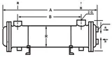
A water-cooled oil cooler on the return line removes the heat the system produces and keeps the oil temperature steady. Its water comes through the machine's cooling water manifold, so a closed or blocked water circuit soon shows as hot oil.
Hydraulic oil
The hydraulic oil transmits the power, lubricates the pumps and valves and carries heat away. Its grade, cleanliness and temperature decide how long the pumps, valves and seals last. Our article on hydraulic oil problems covers dirt, overheating, air and water in the oil.
Common hydraulic problems and their symptoms
- Pressure loss or weak movements: clamp force or injection pressure below the setting, slow movements, longer cycles. Typical causes are a worn pump, a relief or proportional valve that does not hold, internal leakage in a valve or cylinder, a blocked suction filter or a low oil level.
- Oil running hot: a relief valve passing oil, internal leakage in worn parts, too little cooling water or a fouled cooler.
- Noisy pump: a whine or rattle from cavitation (blocked suction filter, low level, cold and thick oil, a closed suction valve), air drawn in through a suction leak, a worn pump or a worn coupling.
- Jerky or unstable movements: air in the oil, a sticking valve spool, a faulty proportional valve or amplifier, a low accumulator pre-charge, or a faulty pressure transducer on a servo machine.
- A movement does not happen: no output from the controller, a burnt solenoid coil, a stuck spool or cartridge valve.
- A cylinder drifts or does not hold: a leaking check valve or cartridge valve seat, or worn piston seals.
- External leaks: hoses, fittings, the O-rings under valves and the pump shaft seal.
Work from the supply outward: check the oil level, temperature and filter first, then the pressure at the pump outlet, then the valves and cylinders of the faulty movement. Our guide to troubleshooting hydraulic pressure loss gives a step-by-step test.
What to send for a replacement quote
- The machine brand, model and serial number, and whether it has a fixed pump, a variable pump or a servo pump.
- The model code from the part's nameplate. On pumps and valves it gives the series, size, control and options.
- Photos of the part from several sides, its nameplate and its connections: ports, flange, shaft and electrical plug.
- For valves, the coil voltage (AC or DC) and the connector type. For pumps, the direction of rotation, the shaft and the flange. For accumulators, the volume and the oil port.
- The page of the hydraulic circuit diagram that shows the part, if you have the manual.
Browse our hydraulic pumps and motors, control valves and accumulators, then request a quote with these details.
Maintenance of the hydraulic system
- Check the oil level and temperature every day. A level that keeps dropping means a leak.
- Change the filter elements at the interval in the machine manual, and every time a pump or valve fails, because its debris stays in the circuit.
- Change or test the oil at the manual's interval, use the grade it specifies, and do not mix brands.
- Keep the cooling water clean and flowing through the oil cooler.
- Check the accumulator pre-charge at the interval in the manual, always with the oil side drained.
- Keep the circuit clean whenever it is opened: cap ports and hoses, clean mounting faces, and fill a new pump with oil before starting it.
- Record the pump outlet pressure, oil temperature and movement times while the machine is healthy, so you have figures to compare with later.
Updated by the IMSPARES technical team.