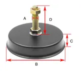
The machine feet are the adjustable supports under the base of an injection molding machine. At each mounting point a leveling foot bolt passes through the base frame and stands on an anti-vibration pad on the floor. Together they carry the weight of the machine and the mold, let you set the machine level, and stop the vibration and shock of the clamp, the injection unit and the pump from spreading into the floor. In the drawing above they are the bolts and rubber pads under the machine base.
What the machine feet do
- Carry the load evenly. Each foot takes a share of the weight of the machine, the mold and the oil in the tank. The shares are not equal, and the manufacturer's foundation drawing shows where the feet go and often the load at each one.
- Keep the machine level and untwisted. The base frame is long. If one foot carries too little, the frame can twist slightly even when a level reads correctly in one place, and the alignment of the platens, the tie bars, the injection unit carriage and the nozzle depends on it.
- Absorb vibration and shock. Fast mold movements, injection, the motor and the pump all produce vibration. The rubber pads absorb part of it, which lowers the noise and the load passed into the floor and to nearby equipment.
- Hold the machine in place. The grip of the pads on the floor stops the machine creeping during fast movements. Some machines are anchored to the foundation instead; the manufacturer's installation instructions say which your machine needs.
How the feet work in the cycle
During every cycle the machine is pushed back and forth by its own movements. The moving platen and the mold half on it accelerate and stop each time the clamp opens and closes, the injection unit moves forward and back, and the screw injects. These forces pass through the base frame into the feet. The rubber in the pads flexes slightly and damps them, and the friction between the pads and the floor keeps the machine where it is.
The feet themselves do not move once the machine is leveled. Their job is to stay put, keep every point of the base supported, and keep doing so as the rubber ages.
The parts of the machine feet
Leveling foot bolt
A threaded steel bolt fitted through a mounting hole or a threaded boss in the base frame, with a lock nut. Turning it raises or lowers that point of the machine, and the lock nut holds the setting. The thread size depends on the machine; the leveling foot bolts we supply are made of 45# (medium-carbon) steel in threads from M20 to M48. See leveling pads and bolts.
Anti-vibration pad
A rubber pad combined with a steel plate, placed under each leveling bolt. The rubber damps vibration and grips the floor, and the steel plate spreads the load and gives the bolt a seat. Pads come in different sizes and hardnesses for different loads. We supply round-base and flower-base (leveling) types in 40–65 Shore A: see the anti-vibration foot pads and the anti-vibration pads page.
Base frame and mounting points
The welded steel base carries the clamping unit, the injection unit and, on hydraulic machines, the oil tank and the power unit. The feet are fitted at the points the manufacturer designed for them, where the frame is stiffened to carry the load. Do not add, remove or move feet without the manufacturer's advice.
Floor and foundation
The feet are only as good as the floor under them. It must be flat, sound concrete that can carry the machine's weight; cracks, slab joints or hollow spots under a foot let it sink or rock. For heavy machines the foundation drawing may call for a dedicated foundation, and new concrete must be allowed to cure for the time the instructions give before the machine is set on it.
Leveling procedure
The machine is leveled by turning the bolts, in small steps, while measuring with a precision level on the reference surfaces the manufacturer names, until it is level along its length and across its width with every foot carrying load. The full method is on the leveling procedure page.
Common problems and their symptoms
- The machine rocks, or one bolt turns freely. That foot is not carrying load, so the others carry more and the frame may be twisted.
- The machine creeps across the floor. The pads are worn, hardened or oily, a foot is unloaded, or the floor under them is contaminated.
- More vibration or noise than before. Hardened or cracked pads, a loose lock nut, or a foot that has lost contact with the floor.
- The level drifts. The pads have settled or flattened, a lock nut has worked loose, or the floor has moved.
- Nozzle and sprue bushing no longer line up, or the injection unit carriage runs unevenly. A base that is out of level or twisted is one possible cause among several. See the nozzle and linear guide pages.
- Platens out of parallel or uneven wear in the tie bar bushings. Check the level before adjusting the clamp: see platen parallelism.
- Swollen, soft or sticky pads. Oil from a leak has reached the rubber. Many rubber compounds soften in contact with mineral oil, so fix the leak and replace the pads.
- A bolt that cannot be turned. The thread has corroded or seized, often from cooling water or cleaning water standing around the feet.
What to send for a replacement quote
- The machine brand, model, serial number and weight, as given on its specification sheet.
- The number of feet.
- For the bolts: thread size and pitch, overall length, the shape of the end that sits on the pad, and the lock nut size.
- For the pads: type (round or flower base), outside diameter, height, and how the bolt sits on the pad.
- Photos of an old bolt and pad in place and removed.
Request a quote with these details, or contact us if you are not sure what your machine uses.
Maintenance that keeps the machine level
- Check the level after installation, again after a period of running because new pads settle, and then at planned maintenance stops.
- Check it again after the machine has been moved, after work on the floor, or whenever alignment problems appear.
- Check that every foot carries load: a bolt that turns by hand is carrying nothing.
- Keep the lock nuts tight, holding the bolt with a second wrench so the setting does not change.
- Keep the area under the machine clean and dry, fix oil and water leaks that reach the feet, and wipe oil off the pads.
- Look at the rubber for cracks, hardening, swelling or flattening, and replace worn pads as a set.
- Put anti-seize compound or grease on the bolt threads when you fit them, so they can still be turned years later.
For the clamp parts shown in the same drawing, see the toggle mechanism guide.
Updated by the IMSPARES technical team.