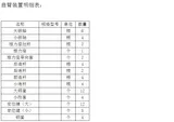
The tie bars of an injection molding machine are the four steel bars that run through the corners of the platens and join the stationary platen to the rear platen. They do two jobs: the moving platen slides along them as the mold opens and closes, and when the mold is clamped they stretch slightly and hold the full clamping force. The numbered drawing above shows the tie bar assembly of a toggle machine; this guide explains each part, how it wears and what to send when you need a replacement.
How the tie bars work in the cycle
The tie bars are loaded and unloaded on every shot:
- Mold closing. The toggle pushes the moving platen forward. It slides along the tie bars on its bushings, which keep it square to the stationary platen.
- Clamping. When the mold halves touch, the toggle keeps pushing until it locks. The moving platen presses the mold against the stationary platen, and the rear platen is pushed backward with the same force. The tie bars join the two outer platens, so they are pulled in tension and stretch elastically, like very stiff springs. That stretch is the clamping force: the more the bars stretch, the higher the force.
- Injection and hold. The melt pressure in the cavity tries to push the mold open. The stretched tie bars hold it shut.
- Mold opening. The toggle folds, the bars return to their original length and the moving platen slides back.
Because the bars stretch and relax on every cycle, they work under fatigue loading for their whole life. Cracks, when they come, start where the stress is concentrated: thread roots, the step from the plain shaft to the thread, and corrosion pits or scratches on the surface.
On a toggle machine the stretch is set by the mold height adjustment, which moves the rear platen along the bars; the toggle guide explains how the links produce the force. Two-platen machines have no rear platen: the moving platen locks onto the tie bars with split nuts, and clamp cylinders build the force by pulling on the bars.
The parts of the tie bar assembly
Tie bar
A long bar of high-strength alloy steel, ground and hardened or chrome plated where the bushings slide on it, with a thread or grooves at each end. Its diameter and the space between the bars are fixed by the machine design and decide how large a mold the machine can take (see Tie bar distance and mold size below). We supply single tie bars and matched tie bar pairs.
Tie bar nut
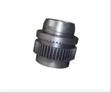
The large threaded nut that holds each tie bar in the stationary platen. It carries the clamping load of its bar through a few heavily loaded threads, so it must be fully engaged, seated square and locked. See the tie bar nuts guide and the tie bar nut we supply.
End cap and lock ring
Fitted over the end of the bar outside the nut. The lock ring stops the nut from turning under the repeated load, and the cap keeps dirt and water off the thread. A loose or missing lock ring is one of the first things to check when the clamping force drifts on one corner. See the tie bar end cap and lock ring.
Tie bar bushing
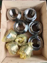
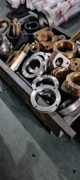
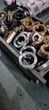
Flanged bronze or self-lubricating bushings in each bore of the moving platen. They guide the platen along the bars and, on many machines, carry part of its weight and the weight of the mold half. Worn bushings let the platen drop and rock, which damages the bars and the mold. See the tie bar bushings guide and our tie bar bushings.
Liner bushing
A plain bronze sleeve that lines a platen bore, such as the rear platen bores in the drawing, so the platen can move along the bar without wearing the bar or the cast iron. Liners are covered in the same tie bar bushings guide; see our liner bushings.
Adjustment bushing
The threaded adjusting nut on each tie bar behind the rear platen. Turning all four together moves the rear platen and the toggle along the bars to suit the mold thickness, and on a toggle machine this is also how the clamping force is set. See mold height adjustment and the adjustment bushing we supply.
Tie bar distance and mold size
The clear space between the tie bars, horizontal by vertical, is one of the first figures on a machine's data sheet. A mold has to pass between the bars to be loaded, so this distance, together with the platen size and the minimum and maximum mold height, decides which molds a machine can run. The tie bar distance page explains how to check whether a mold fits.
Common problems and their symptoms
- Worn tie bar bushings: the moving platen drops at the mold side or rocks when pushed, bronze-colored smears and score marks appear on the bars, and the mold's guide pins wear quickly.
- Uneven load between the bars: flash on one side or one corner of the part, a parallelism error between the platens, and tie bar strain readings (on machines that have them) that differ from bar to bar. Causes include a nut that has turned, adjusting nuts out of step and worn toggle parts.
- Mold height adjustment faults: the adjustment is slow or stalls, the motor runs without the platen moving, or the set clamping force cannot be reached.
- Surface damage: scratches from mold changes and rust pits where cooling water drips on the bars. Both are stress raisers that can start fatigue cracks.
- Cracked or broken tie bar: a crack found during inspection, a bang during clamping, or a sudden loss of clamping force on one corner. Stop the machine: a bar that breaks under load releases a great deal of energy.
Uneven clamping often shows up first as poor platen parallelism, so measure it before replacing parts. Wear in the toggle gives some of the same symptoms.
Inspection and replacement
How to inspect tie bars for wear and cracks, what damages them, and when a bar has to be replaced are covered in our tie bar maintenance and replacement guide. Replacing a tie bar means removing its nuts and drawing the bar out through the platens, then resetting the nuts so that all four bars share the load again. It is a heavy job that needs lifting gear and the manufacturer's procedure, and it is usually done by the manufacturer's service team or an experienced fitter.
What to send for a replacement quote
Tie bar parts are made to suit the machine, so the more of this you can send, the quicker the right part can be identified:
- The machine brand, model and serial number, and its clamping force.
- Which part you need and how many: one bar, a pair, or a full set of bushings.
- For a tie bar: overall length, diameter, the length and position of each thread or groove, and the thread size and pitch at each end.
- For nuts and bushings: bore and outside diameters, length, flange size, thread size and pitch, and the position of grease holes or locking screws.
- Photos of the old part with a tape measure or caliper in view, and the OEM part number or drawing if you have one.
Request a quote with these details, or browse our tie bar parts.
Maintenance that keeps tie bars in service
- Keep the bars clean, and oil them lightly where the manual says so. Wipe off old grease and dirt before it builds up.
- Lubricate the tie bar bushings as the manual specifies, by hand or through the central lubrication system, and check that every point actually receives lubricant.
- Protect the bars during mold changes: a mold that swings into a bar can score it deeply.
- Fix water leaks over the clamp unit quickly, because rust pits on a tie bar are hard to remove.
- Check the nuts and lock rings for movement. A paint mark across each nut and the bar makes a turned nut easy to see.
- Measure platen parallelism, and the load on each tie bar if the machine shows it, at regular intervals and after any work on the clamp unit.
Updated by the IMSPARES technical team.