The injection unit of an injection molding machine melts the plastic and injects it into the mold. It is made of the plasticizing unit (nozzle, barrel head, barrel, screw, screw tip and check ring, and the heater bands around them), the injection cylinder and piston rod that drive the screw forward, the plasticizing motor that turns the screw, and the carriage that moves the whole unit to and from the mold on guide columns or linear guides. The numbered drawing shows the plasticizing unit and injection cylinder in section; this guide explains how the injection unit works as a whole, how its mechanical and hydraulic parts wear, and what to send for a replacement.
What the injection unit does in the cycle
- Carriage forward. Carriage cylinders move the injection unit forward until the nozzle touches the sprue bushing of the mold, then hold it there with the nozzle contact force so the melt cannot leak at the joint.
- Injection. Oil flows into the injection cylinder, which drives the screw forward like a plunger. The check ring closes and the melt is pushed into the mold at the set speeds.
- Hold pressure. At a set screw position, pressure or time, the machine switches from speed control to pressure control and holds pressure while the part cools and shrinks.
- Recovery (plasticizing). The plasticizing motor turns the screw. Melt collects in front of it and pushes the screw back, against the back pressure held in the injection cylinder, until the shot size is reached.
- Decompression. The screw is pulled back a short distance to relieve the melt pressure, so the nozzle does not drool.
- Carriage back (when the process needs it), to break the sprue or to purge.
How the barrel and screw melt the plastic is explained in the barrel and screw guide; this guide covers the parts that move them.
How injection speed and pressure are controlled
On a hydraulic machine, the oil flow into the injection cylinder sets the injection speed, and the oil pressure sets the injection and hold pressure. Proportional valves, or a servo-driven pump, adjust both through the cycle; see proportional valves and the hydraulics guide.
The pressure on the melt is higher than the oil pressure. The injection cylinder's piston area is much larger than the cross-section of the screw, so the force from the oil is concentrated on a smaller area: melt pressure equals oil pressure multiplied by the intensification ratio, the ratio of the two areas. The ratio depends on the cylinder and the screw diameter: on the same injection unit, a smaller screw gives a higher injection pressure and a larger screw a bigger shot.
A linear position transducer measures the screw position for the shot size, the switchover to hold and the cushion.
Electric machines replace the injection cylinder with a servo motor and a ball screw, and the plasticizing motor with a second servo motor. The sequence is the same.
The parts of the injection unit
Nozzle, barrel, screw and check ring
The plasticizing unit: the nozzle, the barrel front flange, the barrel, the screw, and the screw tip and check ring, items 1 to 5 in the drawing. They are covered in the barrel and screw guide linked above and its pages on the screw, the check ring and the nozzle.
Heater bands
The bands around the barrel and nozzle, each zone with its own thermocouple, bring the plastic to processing temperature. See the heaters guide.
Hopper and feed throat
Pellets fall from the hopper through the water-cooled feed throat onto the screw. See hopper and feed throat.
Injection cylinder
Item 8 in the drawing: a double-acting hydraulic cylinder that drives the screw forward to inject, holds pressure, and provides back pressure during recovery. Some machines have one cylinder in line with the screw; many have two cylinders side by side. Worn seals cause slow, weak or uneven injection. See the injection cylinder page.
Injection piston rod
The hardened, chrome-plated rod that joins the injection piston to the moving plate and carries the injection force. Its surface runs through the rod seals, so scoring or pitting on it causes oil leaks. See the injection piston rod page.
Plasticizing motor
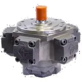
The low-speed, high-torque hydraulic motor that turns the screw during recovery. Its speed sets the screw speed, and its torque must overcome the resistance of the plastic. See the plasticizing motor page.
Guide columns and bushings
On many twin-cylinder injection units, the moving plate carrying the screw drive slides on guide columns through bushings, which keep it square to the barrel. Worn bushings let the plate rock and load the screw and the seals unevenly. See guide columns and bushings.
Linear guide and carriage
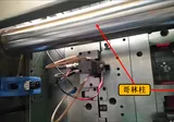
The injection unit carriage runs on guide rails on the machine base, on many machines linear guide rails with ball carriage blocks. They keep the nozzle in line with the mold as the carriage moves. See the linear guide page.
Carriage cylinders
One or two hydraulic cylinders between the machine base and the injection unit. They move the carriage and set the nozzle contact force. Their seals are the same kind of wear part as those of the injection cylinder; see cylinder seal replacement.
Common problems and their symptoms
- Slow or weak injection, or set pressure not reached. Hydraulic supply, valves, or worn injection cylinder seals. See hydraulic pressure loss.
- Cushion varies, or the screw creeps forward during hold. Most often the check ring; then the injection cylinder.
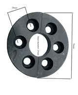
- Screw does not turn, turns slowly or unevenly. The plasticizing motor, its supply valve, a cold barrel zone, or a worn drive coupling.
- Recovery time increases. A worn screw and barrel, a cold zone, or internal leakage in the plasticizing motor.
- Melt leaks between the nozzle and the sprue bushing. Nozzle and sprue radius or orifice mismatch, too little nozzle contact force, or the nozzle off center because of worn guides.
- Carriage moves jerkily or noisily. Dry or damaged linear guides, or worn guide bushings.
- Oil leaks at the cylinders. Worn rod seals or a damaged piston rod.
Measure before replacing: injection time, recovery time, peak injection pressure and cushion, compared with records from when the machine ran well, show which part has changed.
What to send for a replacement quote
- The machine brand and model, and the injection unit size or screw diameter.
- The part name and, if you have it, the OEM part number or the nameplate data (for a motor, its model and shaft type).
- Photos of the old part and its main dimensions: bore and rod diameter and stroke for cylinders, length and thread sizes for rods, rail width and length for linear guides.
- For seal kits, the cylinder bore and rod diameter, or the markings on the old seals.
Request a quote with these details.
Maintenance that keeps the injection unit accurate
- Grease the linear guides and lubricate the guide column bushings as the machine manual specifies; on some machines the centralized lubrication system serves them (see toggle lubrication).
- Wipe the piston rods and check them for scores and rust, especially after a long stop.
- Look for oil leaks at the cylinders, the plasticizing motor and the hoses at every planned stop.
- Check that the lock nuts on the piston rods and the guide column nuts are tight.
- Keep the hydraulic oil clean and at the right temperature; see hydraulic oil problems.
- Check that the nozzle is centered on the sprue bushing after mold changes.
- Record injection time, recovery time and cushion: slow changes over weeks are the earliest sign of wear.
Updated by the IMSPARES technical team.