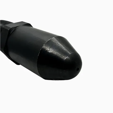
The injection molding screw is the flighted steel shaft that turns inside the heated barrel, melts the plastic and then pushes it into the mold. In every cycle it does two jobs: while it rotates, its flights carry pellets forward from the feed throat and melt them; when it moves forward without turning, it acts as a plunger and injects the melt. The screw's design, its three zones and the condition of its flights decide how evenly the plastic melts and how much of each shot reaches the mold.
The screw is item 4 in the drawing. For how it works with the barrel, the nozzle and the rest of the plasticizing unit, see the barrel and screw guide.
Screw parts names
From the rear (drive end) to the front:
- Shank (drive end). The unflighted rear end that fits into the screw drive. It carries a spline or keys that take the torque from the plasticizing motor, and a groove or collar by which it is held in the drive coupling.
- Flight. The helical ridge wound around the screw. Its outer surface, the flight land, runs close to the barrel bore; the outside diameter of the flights is the screw's nominal diameter.
- Channel and root. The channel is the space between the flights; its bottom is the root. The channel depth is the flight diameter minus the root diameter, divided by two.
- Pitch (lead). The distance from one flight to the next along the screw. Many general-purpose screws have a pitch equal to the diameter, called a square pitch.
- Front end. The thread that takes the screw tip, and the face against which the seat ring of the check ring is clamped.
The three screw zones
The root diameter of the screw changes along its length, which divides it into three zones. The drawing marks them below the screw.
Feed zone
The rear zone, under the feed throat. Its channels are deep and of constant depth, so they can take in loose pellets and carry them forward as solids. The plastic starts to heat up here from the barrel wall. On a general-purpose screw the feed zone is usually the longest of the three.
Compression (transition) zone
The root diameter increases, so the channel gets shallower. This compacts the pellets, squeezes the air between them back toward the hopper, and forces the plastic against the hot barrel wall. Most of the melting happens here, from the heat of the barrel and the shear of the turning screw.
Metering zone
The front zone, with shallow channels of constant depth. It finishes melting, evens out the temperature, and delivers a uniform melt to the space in front of the screw tip.
The ratio between the feed and metering channel depths is the compression ratio, and the flighted length divided by the diameter is the L/D ratio. Both are explained in L/D ratio and compression ratio.
Screw types and screw design
| Screw type | What is different | Typical use |
|---|---|---|
| General-purpose | Single flight, feed, compression and metering zones | Most unfilled and lightly filled plastics |
| Material-specific | Zone lengths and compression chosen for one material, such as a gentle, gradual compression for heat-sensitive plastics or a short compression zone for materials that melt over a narrow range | Rigid PVC, nylon and other demanding materials |
| Barrier screw | A second flight separates melted plastic from unmelted pellets | Higher outputs and more even melting |
| Screw with mixing section | Fluted, pin or ring mixing elements near the front | Color and additive mixing |
| Vented (two-stage) screw | A decompression section under a vent in the barrel lets moisture and gases escape | Materials that release volatiles, used with a vented barrel |
Screws are also chosen for their surface. Nitrided alloy steel suits most plastics; screws for glass-filled, mineral-filled or corrosive materials have hard-faced flights, coatings or tool-steel construction. The injection screws we supply are made in a standard nitrided version and a bimetallic version; see bimetallic barrels for how bimetallic screws differ.
Signs of screw wear and their causes
Symptoms that point to the screw:
- Screw recovery takes longer at the same screw speed and back pressure.
- Shot weight and cushion vary even after the check ring has been replaced.
- More black specks, streaks and slower color changes.
- Unmelted pellets in parts at outputs the machine used to handle.
- Visible scoring, polished bands or chipped edges on the flights when the screw is pulled.
The usual causes:
- Abrasion from glass fiber, minerals and some pigments, which wears the flight lands and opens the clearance to the barrel.
- Corrosion from plastics or additives that release corrosive gases when they overheat.
- Adhesive wear (galling) when steel rubs on steel: a bent screw, a misaligned barrel or running the screw with an empty barrel.
- Overload from turning the screw on plastic that is not fully melted, which can twist the screw or break the tip.
- Foreign metal in the material, which scores the flights. A hopper magnet catches loose iron and steel.
Inspecting and measuring an injection molding screw
- Pull the screw while the barrel is hot (see how to remove the screw) and lay it on supports along its length.
- Clean it while it is still warm, with brass brushes and scrapers that will not mark the flights.
- Look for scoring, pitting, cracks at the root of the flights, wear on the drive spline or keys, and damage to the tip thread.
- Check straightness by rolling the screw on V-blocks with a dial indicator.
- Measure the flight diameter with a micrometer at intervals along each zone and compare it with the nominal size and with the barrel bore.
Our guide to measuring barrel and screw wear explains how to interpret the readings. A screw with worn flights can sometimes be rebuilt by hard-facing and regrinding; a bent or cracked screw should be replaced.
What to send for a replacement screw
- The machine brand and model, and the injection unit size or screw code if you know it.
- The screw diameter and the plastics you run, including fillers.
- The overall length, the flighted length and the lengths of the three zones (or the number of flights in each).
- The root diameters in the feed and metering zones, and the pitch.
- The drive end: spline or key, with its dimensions, and the tip thread size and hand.
- Photos of the whole screw and both ends, and the OEM part number or a drawing if you have one.
Request a quote with these details. If the barrel is worn too, quote the screw and barrel as an assembly.
Updated by the IMSPARES technical team.