The toggle mechanism is the linkage between the rear platen and the moving platen of a toggle-type injection molding machine. The clamping cylinder pushes a crosshead, the crosshead drives short connecting links, and these fold or straighten the main toggle links. Straightening the links closes the mold; as they come into line, they multiply the cylinder's force into the full clamping force and hold the mold shut while the plastic is injected. The drawing above shows a five-point double toggle, a common design on small and medium machines, with each part numbered.
For the principle in more depth and how a toggle wears over the years, see our article Understanding your machine's toggle clamping system. This guide describes each part of the toggle mechanism, the problems they cause, and what to send when you need a replacement.
How the toggle mechanism works in the cycle
- Mold close. The clamping cylinder pushes the crosshead forward and the links start to straighten. The moving platen starts slowly, travels fastest in the middle of its stroke and slows down again as the links approach the straight position. Before the mold halves touch, the controller switches to a low-pressure mold protection stage, so that a part left in the mold stops the clamp instead of being crushed.
- Lock-up. In the last part of the stroke the mold halves already touch, and the links are pulled straight against the resistance of the tie bars. The tie bars stretch elastically, like very stiff springs, and their stretch is the clamping force. At or very close to the straight position the links hold the load themselves, so the cylinder needs little force to keep them there.
- Injection and hold. The melt is injected and packed while the toggle stays locked. The pressure in the cavity tries to push the mold open; as long as the force it produces is lower than the clamping force, the parting line stays closed.
- Mold open. The cylinder pulls the crosshead back and the links fold. The platen first breaks the mold open slowly, then moves fast, then slows again before the open position, where the part is ejected.
Why the clamping force depends on the mold height
On a toggle machine the clamping force is not set by the cylinder pressure. It is set by the position of the rear platen. The mold height adjustment moves the rear platen, and the whole toggle with it, along the tie bars, so that the mold halves touch a set distance before the links are straight. The earlier they touch, the more the tie bars must stretch and the higher the clamping force. Many controllers make this adjustment automatically when you enter a clamping force. See mold height adjustment for the mechanism, and how to calculate clamping force for how much a mold needs.
Because the setting depends on dimensions, anything that changes them changes the force: the mold growing as it heats up, and wear in the pins and bushings, which shortens the linkage slightly. Check the clamping force again once the mold is at temperature.
Toggle or direct hydraulic clamp?
| Toggle clamp | Direct hydraulic clamp | |
|---|---|---|
| How the force is made | Links multiply the force of a smaller cylinder | A large cylinder presses on the platen directly |
| How the force is set | Mold height adjustment (tie bar stretch) | Hydraulic pressure |
| Movement | Fast mid-stroke, slowing naturally at both ends | Set by the hydraulic circuit |
| Main wear points | Many pins and bushings that need lubrication | Few moving joints; cylinder seals |
The parts of the toggle mechanism
Clamping cylinder
The hydraulic cylinder mounted on the rear platen. Its piston rod pushes the crosshead forward to close the mold and pulls it back to open it. Because the toggle multiplies its force, it is much smaller than the cylinder of a direct hydraulic clamp of the same size. Leaking piston or rod seals make clamping slow or weak: see the clamping cylinder guide and the clamping cylinder we supply.
Crosshead
The block on the end of the cylinder rod. It moves in a straight line along the machine axis and drives the upper and lower toggles at the same time through the short connecting links, so that both straighten together. Wear in its connection to the rod or in its bushings shows as a knock at each change of direction. See the crosshead page and the toggle link and crosshead parts we supply.
Toggle links
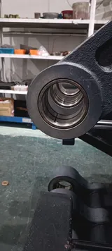
The steel links, also called toggle arms, that form each toggle: a rear link pinned to the rear platen and a front link pinned to the moving platen, joined at the elbow, plus the short link from the crosshead. They fold to open the mold, straighten to close it, and carry the clamping force in compression when locked. See toggle links and our toggle arms and link rods.
Toggle bushings and connecting rod bushings
Bronze or self-lubricating sleeves pressed into the link bores, where the links turn on the pins. They are softer than the pins and meant to wear first. The bushings in the short links between the crosshead and the toggle links are called connecting rod bushings. See toggle bushings and our toggle link bushings, toggle pin bushings and connecting rod bushings.
Toggle pins
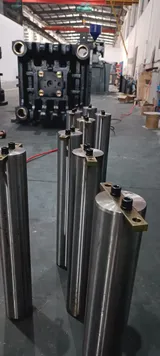
Hardened, ground pins that join the links at every pivot, five on each toggle of a five-point design. At lock-up the whole clamping force passes through them, so they need a steady supply of lubricant. See toggle pins and the toggle hinge pins we supply.
Lubrication system
A centralized system that pumps oil or grease through distributors and tubes to every pin and bushing, and on many machines to the tie bar bushings and platen slides too, at an interval set in the controller. When it fails, the joints run dry and wear quickly. See toggle lubrication.
Platens, tie bars and mold clamps
The toggle works between the rear platen and the moving platen, and the four tie bars carry its force back to the stationary platen. The mold halves are held on the platens by mold clamps and centered by the locating ring. See the guides to the platens, the tie bars and the mold clamps. The leveling bolts and anti-vibration pads under the base are covered in the machine feet guide.
Common toggle problems and their symptoms
- Flash on parts that used to run clean. The clamping force has dropped: the mold height setting has drifted, the mold temperature has changed, or wear in the joints has shortened the linkage. Check the actual force before blaming the mold.
- Knocking at mold close, at lock-up or when the mold breaks open. Play in the pins and bushings, a loose crosshead connection, or closing into lock-up too fast.
- Uneven clamping, or flash on one side of the mold. Unequal wear between the upper and lower toggle, tie bar nuts out of step, or platens out of parallel. See platen parallelism.
- Squealing, dry joints, or dark and gritty lubricant at a joint. The lubricant is not reaching that joint.
- The clamp stops before lock-up or does not reach the set force. The mold height is set too tight for the mold, or something is blocking the movement.
- Slow or jerky opening and closing. Often a hydraulic fault rather than the toggle itself: see troubleshooting hydraulic pressure loss.
- A cracked link or a broken pin. Usually overload or fatigue after long running with worn joints. Stop the machine at once.
To measure the play at each joint with a dial indicator, follow the method in the toggle clamping system article linked at the top of this guide.
What to send for a replacement quote
- The machine brand, model, clamping force and serial number: toggle parts can change between production years of the same model.
- Which parts and which positions (upper or lower toggle; rear, elbow, front or crosshead pivot), and how many.
- Photos of the old parts with their main dimensions: for pins, the diameter and length; for bushings, the outside and inside diameters and the length; for links, the distance between bore centers and the bore diameters.
- The OEM part number or the page of the parts list from the machine manual, if you have it.
Request a quote with these details, or contact us if you are not sure which part you need.
Maintenance that keeps the toggle in shape
- Keep the lubricant reservoir filled with the grade in the manual, and never keep running with a lubrication alarm.
- At planned stops, look at every joint: it should show a thin film of fresh lubricant, not dry metal or dark, gritty paste.
- Use the lowest clamping force that molds good parts. Extra force loads the pins, bushings, links and tie bars on every cycle without improving the parts.
- Use the mold protection stage and a slow approach to lock-up; closing at full speed into lock-up hammers every joint.
- Mount molds centered on the platens, so that the upper and lower toggles share the load.
- Record joint play and tie bar stretch at planned stops, so you can see wear developing, and replace bushings before the pins start to wear.
Updated by the IMSPARES technical team.