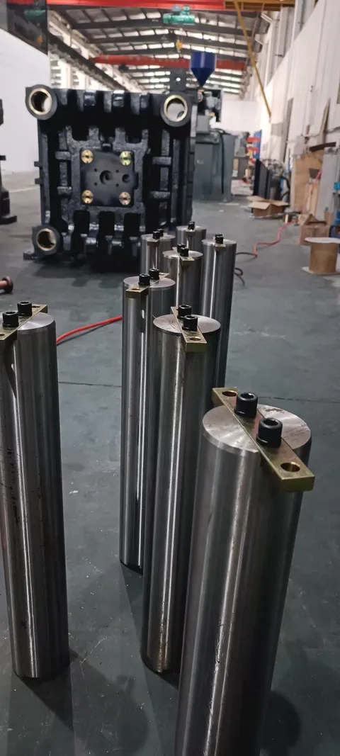
An injection molding machine toggle pin, also called a hinge pin, is the hardened steel pin at each pivot of the toggle clamp, on which the links turn. On a five-point double toggle each toggle has five pivots: at the rear platen, at the elbow between the links, at the moving platen, and at both ends of the short link to the crosshead. When the toggle locks, the whole clamping force passes through these pins, so their condition, and the lubricant that reaches them, decides how long the toggle lasts. The drawing shows the pin at every pivot of the upper and lower toggle.
How a toggle pin works
The pin passes through the bores of the two parts it joins. On many designs it is held still in one of them, and the other turns on it through a bronze or self-lubricating bushing. A retaining plate, bolt, end cap or circlip stops the pin turning or sliding out; the design varies between machines.
The pin carries the load in shear and bending, and passes it to the bushing as pressure on the bushing bore. The motion is not a full rotation but a swing through a limited angle, twice per cycle, with the highest load at the end of the stroke when the links straighten. Under that kind of motion a lubricant film does not build up by itself, so the joint needs fresh lubricant fed to it regularly. Many pins have a drilled passage that carries the lubricant from a fitting on the pin end to holes or grooves where the bushing runs. See toggle lubrication.
Materials and variants
Toggle pins are made of hardened steel with a ground surface, often chrome plated. The toggle hinge pins we supply are GCr15 bearing steel or 42CrMo alloy steel, ground, hardened to HRC 58–63 and chrome plated, for Haitian MA, MA II and MA III machines.
Pins differ in diameter and length between positions on the same machine, and in how they are retained and lubricated: plain or stepped, with or without a lubrication passage, with a slot for a retaining plate, a threaded end or a groove for a circlip. Always match the replacement to its position.
Signs of a worn toggle pin
- A knock at lock-up or when the mold breaks open.
- Play at the joint when the clamp is depressurized.
- Scoring, galling or a worn step on the pin where the bushing runs.
- Pitting, peeling chrome or rust on the surface.
- Blue or brown discoloration, a sign that the joint has run hot and dry.
- Bronze-colored particles in the lubricant around the joint, from the bushing wearing against the pin.
- A pin that turns in a bore where it should be fixed, or loose or sheared retaining bolts.
The usual causes are lubrication failure, dirt in the lubricant acting as an abrasive, worn bushings that let the pin take impact loads, a clamping force set too high, and misalignment between the toggles.
Measuring a toggle pin
The quickest check, the play at each joint measured with a dial indicator while the pin is in place, is described in our toggle clamping system article. When the pin is out:
- Clean the pin and measure it with an outside micrometer at several points along its length, both where the bushing runs and where it does not; the unworn section gives you a reference.
- At each point, measure in two directions at right angles to find any ovality.
- Measure the bushing bore with a bore gauge in the same way.
- The running clearance is the bore diameter minus the pin diameter. Compare it, and the pin wear, with the limits in the machine manual.
Replacing a toggle pin
- Remove the mold, or make sure the toggle carries no clamping load. Switch off, lock out and release the hydraulic pressure, including any accumulator.
- Support the links, and the moving platen if the manual says so, with lifting gear or blocks so that no weight rests on the pin.
- Disconnect the lubrication line or fitting and remove the retaining plate or other retainer.
- Push the pin out with a puller or a press. If it must be driven, use a soft drift of brass or aluminum: hammering directly on a hardened pin can chip it.
- Clean the bores and the lubrication passages, inspect the bushings and replace them if they are worn.
- Coat the new pin with the lubricant the manual specifies, line up its lubrication holes with those in the bushing, fit it and refit the retainer.
- Run the lubrication manually until fresh lubricant appears at the joint, then cycle the clamp slowly and listen for noise. Check the mold height and clamping force before production.
If the pin is worn, replace it together with its bushings; if it is smooth and within limits, new bushings alone are usually enough.
What to send for a replacement quote
- The machine brand, model, clamping force and serial number, and which pin positions you need.
- The pin diameter (or diameters, for a stepped pin) and overall length.
- How it is retained (plate slot, thread or circlip groove) and where the lubrication passage and holes are.
- Photos of the old pin and, if you have it, the OEM part number.
For how the pins fit into the rest of the clamp, see the toggle mechanism guide and the toggle links page.
Updated by the IMSPARES technical team.