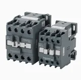
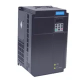
The electrical system of an injection molding machine powers every motor and heater and controls every movement of the cycle. A controller in the electrical cabinet reads the safety switches and position sensors, steps through the cycle, and sends commands to the hydraulic valves, the heater zones and the servo drive that runs the pump motor. The numbered drawing above shows the main parts; this guide explains what each one does, the faults that stop a machine, and what to send when you need a replacement.
How the electrical system works in the cycle
The electrical system has two jobs: distributing power and controlling the machine.
Power. The three-phase supply enters the electrical cabinet through the main isolator switch. From there it feeds the servo drive (or the starter of the pump motor on a fixed-speed hydraulic machine), the contactors or relays of the heater zones, and the power supplies that produce the low DC voltages for the electronics. The boards, sensors and valve coils usually run on 24 V DC.
Control. The controller repeats the same sequence every cycle, and each step waits for a signal from a sensor:
- Gate closed. The safety gate switches tell the controller that the gate is shut. Only then will it close the mold.
- Mold close. The controller switches the clamp valves and commands the pump speed and pressure. A position sensor reports where the moving platen is, so the controller can change to low speed and low pressure for mold protection before the mold halves touch.
- Injection and hold. The controller drives the screw forward and switches from injection speed to hold pressure at a set screw position, pressure or time.
- Screw recovery. The screw turns to plasticize the next shot until the injection position sensor reports the set shot size.
- Mold open and ejection. The controller opens the mold to the set position and moves the ejector; a sensor confirms that the ejector is back before the next cycle starts.
Throughout the cycle, the controller reads the thermocouples and switches the heater bands to hold each barrel zone at its set temperature. Our article on how injection molding works explains the cycle itself in more detail.
On a servo-hydraulic machine, the servo motor drives the hydraulic pump and changes its speed so that each step gets the flow and pressure it needs; while the machine waits, the motor slows down or stops. All-electric machines use separate servo motors for the clamp, injection, screw rotation and ejector, but the control principle is the same.
The parts of the electrical system
Operator panel
The screen and keys where the operator enters temperatures, speeds, pressures, positions and times, stores the settings for each mold and reads alarms. It talks to the CPU board in the cabinet over a cable. See the control panel guide, which also covers the electrical cabinet behind it.
Controller (main CPU board)
The CPU board runs the machine program: it reads the inputs, steps through the cycle and sets the outputs. It sits in the cabinet with the I/O, drive interface and power supply boards, shown together as the controller boards in the drawing. Machines use controllers from various makers, and the controller model is printed on the boards and on the operator panel. See the controller guide.
I/O modules
I/O modules connect the CPU to the machine. Inputs come from switches, sensors and buttons; outputs go to valve solenoids, contactors and heater relays. A failed channel usually stops one function only. See the I/O module guide.
Power supply board
Turns the cabinet supply into the regulated DC voltages that the boards, sensors and valve coils run on. A weak supply causes faults that look like failures of other boards. See the power supply board guide.
Drive interface board
Passes the speed and pressure commands from the CPU to the servo drive or frequency inverter and reads back its status. See the drive interface board guide.
Servo drive
The power electronics unit that powers and controls the servo motor. It turns the mains supply into DC and then into a variable three-phase output, using the motor's encoder to control speed and torque. See the servo drive guide.
Servo motor
A permanent-magnet AC motor. On servo-hydraulic machines it drives the hydraulic pump through a flexible coupling. See the servo motor guide, and the servo pump guide for the hydraulic side.
Encoder
The sensor at the rear of the servo motor that measures the position and speed of the shaft. The drive cannot run the motor without it, so an encoder or encoder cable fault stops the pump. See the encoder guide.
Capacitors
Electrolytic capacitors store energy on the DC bus of the servo drive and smooth its voltage; film capacitors filter electrical noise. Electrolytic capacitors age with heat and time and are a common cause of drive faults. See the capacitors guide.
Safety gate and safety gate switch
The safety gate is the sliding guard over the mold area. Switches pressed by the gate tell the controller that it is closed; until they do, the mold will not close. See the safety gate guide.
Limit switches
Mechanical switches with a roller lever or plunger that a cam presses at a set position. They are used on the safety gate and to detect the ends of travel. See the limit switch guide.
Proximity sensors
Inductive sensors that switch when a steel target comes close, without touching it. They detect platen and ejector positions and are used for mold protection. See the proximity sensor guide.
Linear transducers
Rod or slider sensors along the clamp, the injection unit and the ejector that report position continuously. On many hydraulic machines, the positions you set on the panel are measured by them. See the linear transducer guide.
Heater bands and thermocouples
Ceramic heater bands heat the barrel in zones, and a thermocouple in each zone tells the controller its temperature. They have their own heater bands and sensors guide, including a page on thermocouples.
Common electrical problems and their symptoms
- The mold will not close although the gate is shut: a misaligned or failed safety gate switch, a broken wire, or a worn gate that no longer presses the switch fully.
- Positions jump, or the controller shows a transducer alarm: a worn linear transducer track, a loose mounting or a damaged connector.
- Servo drive alarms (overcurrent, overvoltage, encoder error, overheating): a damaged encoder or motor cable, aged DC bus capacitors, a failed cooling fan, or a motor insulation fault.
- The panel freezes, restarts or loses communication: an unstable power supply, loose connectors, overheating or dust in the cabinet.
- One function does not respond while everything else works: a failed input or output channel, its sensor or valve coil, or the wiring between them.
- Faults that appear only when the cabinet is hot: blocked filters, failed fans and aged capacitors.
- A heater zone that will not reach temperature: a failed heater band, thermocouple or heater relay, or the wiring between them. The heater bands and sensors guide covers the checks.
Before replacing a board, use the alarm history and the input/output monitor page that most controllers provide. It shows whether a switch signal reaches the controller and whether an output is switched on, which separates a failed board from a failed sensor, coil or wire.
Safety in the electrical cabinet
Work inside the electrical cabinet is for qualified electricians. Before any part is replaced, the machine must be switched off at the main isolator, locked out and tagged, and the absence of voltage checked with a meter. Servo drives and power supplies hold a dangerous charge in their capacitors after the supply is off: wait at least the discharge time shown on the drive's warning label or in its manual, and measure the DC bus before touching it. Never bridge or bypass a safety gate switch, even for a test. Boards are sensitive to static electricity, so handle them by the edges with a grounded wrist strap and keep spares in antistatic bags.
What to send for a replacement quote
- The machine brand, model and serial number, and the year if you know it.
- For boards and panels: the controller model printed on the operator panel and the boards, the board's own model number or label, and photos of both sides of the board and its connectors.
- For servo motors and drives: a clear photo of the nameplate (model, power, voltage, speed, current), and for motors the encoder type, the flange and the shaft.
- For switches and sensors: the label, the type (for example PNP or NPN, normally open or normally closed), the thread or mounting, and the connector or cable.
- For capacitors: the printing on the sleeve (capacitance, voltage and temperature rating), the can size and the terminal type.
- The symptom and any alarm code shown on the panel or the drive.
Request a quote or send the details on WhatsApp. Our parts for this zone are listed under electrical components, including circuit boards, servo motors and drives and safety switches and sensors.
Maintenance of the electrical system
- Keep the cabinet doors closed and the filters clean, and check that the cooling fans run. Heat shortens the life of boards and capacitors.
- Keep oil, water and dust out of the cabinet, the operator panel and the sensor connectors.
- During planned shutdowns, with the machine isolated and locked out, have an electrician check the terminals for tightness and discoloration.
- Check the cables that move with the platen, the injection unit and the safety gate for wear.
- Test the safety gate interlocks as often and in the way the machine manual describes, which is often at the start of every shift.
- Back up the mold settings and machine parameters, and record the controller and board models before a fault happens.
- Keep spare boards in antistatic bags in a dry place. Spare servo drives stored without power for a long time may need their capacitors reformed before use; follow the drive maker's instructions.
Our maintenance checklist for Haitian MA machines lists electrical checks alongside the hydraulic and mechanical ones.
Updated by the IMSPARES technical team.