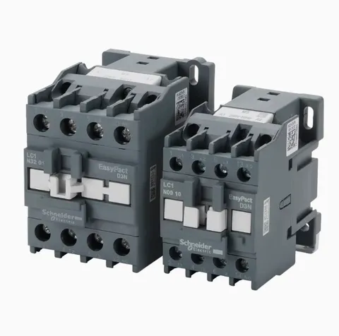
An I/O module (input/output module) is the board that connects the controller's CPU to the machine. Its inputs receive the signals from limit switches, proximity sensors, pushbuttons and transducers; its outputs switch the valve solenoids, contactors and heater relays. The CPU decides what happens in the cycle, and the I/O modules carry those decisions to the machine and bring the machine's answers back.
Where the I/O modules sit
The I/O modules are mounted in the electrical cabinet with the main CPU board. The wiring from the machine lands on the terminal blocks and runs through the cable duct to the modules. Depending on the controller, the modules plug into a rack with the CPU or are separate boards linked to it by a cable or a communication bus.
How an I/O module works
- Digital inputs read on/off signals, usually at 24 V DC: a switch closed or open, a sensor on or off. Each input is normally isolated from the CPU electronics, often by an optocoupler, and has an LED that lights when the signal is present.
- Digital outputs switch loads on and off: valve solenoid coils, relays and contactors, and indicator lamps. They are transistor or relay outputs, and each one normally has its own LED.
- Analog inputs read signals that vary continuously, such as the voltage from a linear transducer or the signal from a pressure transducer.
- Analog outputs send variable commands, for example to a proportional valve amplifier or a servo drive.
- Temperature inputs for the thermocouples are often on separate temperature boards; see barrel temperature control.
Many I/O boards combine several of these types. Our I/O controller board is a 24 V DC board listed for Haitian MA and MA II series machines.
Signs of a failed I/O channel or module
- One function does not work while the rest of the machine does: a valve does not switch, or the controller does not see a switch.
- The output LED lights but the valve does not move. The fault is after the board: the wiring, the connector or the coil.
- The valve should move but the output LED stays off. The controller is not commanding it, either because a condition in the program is not met (for example the gate signal) or because the board has failed.
- An output stays on when it should be off.
- A whole group of channels fails at once, often from a blown fuse, a lost supply or a lost connection to the CPU.
- Burn marks around an output channel or its connector.
Why I/O modules fail
A frequent cause of a damaged output is a fault in the field: a shorted solenoid coil, a pinched cable touching the frame, or a load that draws more current than the output is rated for. Solenoid coils are inductive and produce a voltage spike when they are switched off; a missing or failed suppression diode or suppressor on the coil can damage the output over time. Inputs are damaged by wrong voltages and by water or oil in the wiring and connectors. Heat, dust and loose terminals affect the whole board.
Testing and replacing an I/O module
Measurements and board replacement are for qualified electricians. Replace a board only with the machine switched off at the main isolator and locked out.
- Open the controller's input/output page and watch the channel while operating the switch, or while calling the function in manual mode.
- Compare the page with the LED on the module and, with the machine in a safe state, a meter reading at the terminal block.
- If an output has failed, find and repair the cause in the field first: check the coil resistance and the insulation of its cable. Otherwise the new output may fail the same way.
- Isolate and lock out the machine. Wear a grounded wrist strap, photograph the board, and label the connectors.
- Set any address switches or jumpers on the new board exactly as on the old one, fit it and reconnect.
- Test every input and output on the I/O page before running the machine.
What to send for a replacement quote
- The machine brand, model and serial number.
- The controller model printed on the operator panel and on the board.
- The model number or label of the module, and photos of both sides with the connectors.
- Which inputs or outputs failed, and what they drive.
The solenoid directional valve guide covers the valves that many outputs drive, and the electrical system guide shows where the I/O fits in the machine.
Updated by the IMSPARES technical team.